6m to 10m converter
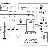
This circuit is based around mixer/oscillator IC2. A 50mHz signal is fed to pin1 input of IC2 and mixed with the local oscillator injected at pin7.
The resultant output is the antenna frequency minus the LO frequency – in this case, 28mHz.
Some constructors have reported 28Mhz breakthrough when receiving 6m signals. To combat this, a Pi-network filter consisting of L3, 47p and 15p components, has been added at the input. This is centered around 51Mhz.
Adjustment:
- Tweak the 22p trimmer for highest signal between 50mHz – 52mHz
- Adjust the 50p crystal trimmer to calibrate your receiver – this has a range of approx. 300Hz
- Set the RF output level with P1 without introducing distortion
Other IF frequencies can be chosen by selecting a different LO crystal frequency. For instance, if you use a 24mHz crystal then: 50mhZ – 24mHz = 26mHz IF output.
| Coil Details | |
|---|---|
| L1 / L2 | 10uH RF choke. |
| L3 | 4 turns 0.6mm close-wound on 8mm drill bit. |
| L4 | 7 turns 1mm silver wire on 9mm drill bit. Tap 1.5 turns from cold end. |
| L5 | 11 turns 0.6mm close-wound on 5mm drill bit. |
For more details of wire thicknesses, see Wire Gauges.
Footnote:
I have been told since this design was uploaded, that good results are obtained using a ‘NE612’ chip. One constructor I know of obtained his from an old and defunct satellite receiver.








Last Comments