A 60′ Tree-Tower for HF Wire Antennas
I put up the first version of this tower in October; made completely out of lumber glued and screwed into structural T-sections. But it fell down….
Actually, it worked fine for a few months, but then we had a 70mph+ windstorm here in December, and it snapped in two places….while I watched. That hurt.
So, in order to avoid the ignomony of having a tiny signal on ’75, I worked out a phase-2 design that would stay up. My thanks to Ray WA9SXJ and Bill N4VMY for advice on guys and guy locations. This new sky-needle has:
- half the wind-resistance
- three times the rigidity
- about the same weight
- easier assembly
- lightning protection (fully conductive)
- could be used as a vertical, if desired
Doing this work in Minnesota, in December and January, is always fun… It can be interesting to work at the top of a 24′ ladder with temps falling to 15 below zero at times, and the wind gusting 20-30 knots. Ah well, that’s what safety-lines are for, right?
And here’s the result….
Sixty feet of big HF signal!
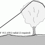
This is another “tree-tower”…my name for using trees to provide the tower foundation and first “section”. No digging, no concrete work. It ain’t a stack of Rohn 55, to be sure, but it’s a lot of tower for only 50 bucks!
Tower Materials & Construction:
This tree was a 4-trunk hard maple. The top of the tower-trunk was lopped off at the 27′ level, with a chainsaw, from the top of a 24′ ladder. The tower is assembled from:
- Maple tree trunk, 27′ tall, tapering from approx. 11″ to 5″ diameter
- Structural-T, fabricated from 2×6 & 2×4 treated lumber
13′ tall, bottom at 20′ level of trunk (7′ overlap) - 2.5″ OD steel structural tubing 10′ tall, overlaps T by 2′
- 2.25″ OD galvanized steel EMT (conduit) 10′ tall, overlaps 2.5″ by 1′
- 1.75″ OD galvanized steel EMT (conduit) 10′ tall, overlaps 2.5″ by 1′
- .25″ steel lightning rod 1.5′ tall on top, welded on.
- The T-section is fastened to the trunk with a pair of ratcheting
fiberglass hold-down straps. The two “boxes” visible in the picture
are only for guiding and stabilizing the tower during hoisting. They are
not part of the tower structure per se.
Guying:
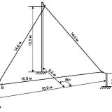
A guy ring was put on at the 45′ level, about halfway up the metal-tubing portion. Three 1/4″ nylon ropes are pulled over to large trees, at about the 20′ level, taken over pulleys, and brought down to cleats mounted on the trees at easy-access level, about 5′; and tied off there after tensioning. I’ve retensioned the guys twice in the past 3 weeks, and they seemed to have stopped stretching. However, I’ll continue to check them each time we have a particularly windy day.
Antennas On This Tower:
- Full size 160m dipole broadside N-S
- Full size 80m/75m dipole broadside E-W
- Full size 40m dipole broadside E-W
- All are on the same feedpoint, same coax, same balun.
- Typical SWR’s are in the 1.3:1 range
- There is a resonance of 3:1 or less in every HF amateur band.
- Halyard pulley at approximately 60′ AGL. Halyard is 1/4″ nylon rope.
- Balun:
After erecting this phase-2 sky needle, I decided to put some effort into improving the antennas themselves, as well. My first step was to add the choke-balun shown here, to keep RF off the feedline. It’s 25′ of RG8-X wound on 4.25″ OD thin-wall PVC pipe.
Tubing Joints:
On the mill, I slit a piece of 1.5″ PVC sched-40 pipe to make a sleeve which fits perfectly between the 1.5″ EMT (1.75″ approx OD) and the 2″ EMT (2.1″ approx ID). A couple of muffler clamps and a 1″ metal strap for electrical connection completes this joint.
The 2″ EMT to 2.5″ structural-tubing joint was made with a 1 foot piece of 2″ EMT slit on the mill and spread a bit to slip over the 2″ EMT section. As such, it’s a perfect slip-fit into the 2.5″ OD steel tubing. A couple more muffler clamps completed this joint as well.
The 2″ to 1.75″ joint… (electrical strap out of view, underneath tubing)
Tubing-to-T Joint:
This shot shows how the bottom tubing section is attached to the lumber T-section, and also clarifies the construction of the T-section itself. The 2×4 is glued and screwed all the way along the 2×6, giving a T-section with equal width in both axes.
The joint itself is a pair of 1″ wide by .100″ thick galvanized steel straps, with nylon locknuts
Also visible in this picture are the three #18 wires stapled down the length of the wood T-section; simulating a 5″ diameter metal tube. These are currently tied off to ground, to complete the lightning rod circuit. They also allow me to use the tower as a vertical in the future, if I decide to try that. Far easier to put them on before the tower went up, then to have to add them later!
Tower Erection:
Sections assembled, winch-rope attached, ready to hoist skywards!
(the ‘ruler’ used for scale reference is approx. 5.5′ long…er…tall…whatever)
I designed in two different hoisting points; one at the top of the T-section, and one at the bottom. There is a 1,500 lb winch mounted at the base of the tree, and a pulley mounted up at the 25′ level on the trunk.
First, the winch-rope is attached to the upper hoisting-ring on the tower assy. A 6-gal can of kerosene was required to properly balance the load (so that the bottom end stayed on the ground as the upper end was lifted into the air).
The winch is operated to tilt the tower up into the air. When vertical, the two “boxes” at the top of the trunk were opened, and the tower placed inside, and the box-doors closed and locked again. These boxes act as guides during the next hoisting step.
At this point a ratchet-strap was used to secure the tower to the trunk. The hoist-rope was moved to the lower hoisting-ring at the very bottom of the the tower assembly, and the strap released.
Now the winch was operated again to inch the tower up the tree. A little jockeying was required to slide the main tubing-to-T joint through the boxes. With the tower in final position, a pair of ratcheting straps were snugged down very securely to fasten it to the tree. Most of the tension was then released from the winch-rope; but a little was left on as a backup measure in case a strap should fail.
At this point, the dipole-junction circuit board was attached to the halyard and headed skyward! Ahhh….success!! I’m big again!! wheeeee!!!!!
tee hee….sorry, I can’t help it….
A Nice Reward for Hard Work!
And after two long cold days of winter tower work, what could be better than a steaming hot sauna at sunset !!
Inside the wood-fired cedar sauna….gawd, we love living here!





Last Comments