Inverted L antenna for Reception
Do to it’s ease of construction, the most popular antenna for short wave reception is the inverted “L” antenna. It’s often just a random length of wire strung up as high as possible.
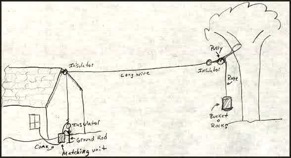
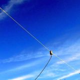
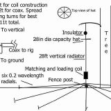
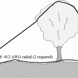
My inverted “L” is 190 feet of 14 gauge galvanized-steel electric fence wire. It’s suspended by electric fence corner insulators between the peak of a roof and a tree. At the tree end, I have connected the insulator to a length of nylon rope that runs over a pulley, which then is secured to a weight.
It’s arranged so the wire remains taught, but will not be broken if the tree sways in the wind. The fence wire is not as good a conductor as stranded copper wire, but it’s very strong, as are the insulators. This antenna has withstood high winds during severe icing conditions… and it’s cheap.
Typically the feedline for an inverted “L” antenna is a single wire that runs under the window sill, and then it attaches to the antenna terminal of the radio. The reception will be good on some bands, and rather lousy on others… this is predominately due to variations of the antenna impedance at different frequencies.
I like using coaxial cable as my feedline in order to to avoid picking up noise from the utility wiring. This makes the losses due to the impedance mismatch even worse. There is a simple solution to this problem that will improve reception remarkably, and without creating the additional problems associated with the use of an amplifier. It’s called a matching transformer.
By using a transformer with a 4:1 impedance ratio, the antenna and feedline impedances are better matched over a broader range of frequencies. In theory a 9:1 impedance ratio should work better, but for the frequencies I’m interested in the 4:1 ratio worked best (1750 – 40 meters.) For general shortwave listening use the 9:1 impedance ratio. Signals that are weak but audible using the wire alone will often come booming in when the transformer is hooked up.
To employ the transformer I needed a connection to ground. The short vertical leg is secured by an insulator, which is tethered to an 8 foot ground rod.
The matching transformer is 6 tri-filiar turns of #26 awg magnet wire wound on a small Magnetics Inc “P” material toriod core. Neither the material, the number of turns, or the geometry of the core is terribly important. For SWL use a material with an mu of 850 to 3,000.
The lower mu will work marginaly better at the high frequencies due to lower material losses. But a higher mu material will improve results on the lower frequencies. At received signal power levels, the losses in the transformer using high mu material at 20Mhz are still less than a decibel. So I decided to use a high mu material to improve results on theAM BCB and below.
To wind the core, first take three lengths of #26 magnet wire that are long enough to make 6 or so turns around the core, and twist them loosely together. Thread them through the core, trying to spread the windings out evenly around the perimeter of the core. Two of the three windings are connected in series between the antenna and ground, the remaining winding is connected between the coax center lead and ground. The coax shield is also grounded. (If you’d like to try a 9:1 impedance ratio, wind with four wires in hand. Then connect three of the windings in series to make the antenna side of the transformer.)
I connected an NE2 neon bulb between the antenna lead and ground to provide some protection from induced lightning transients. If the bulb fires, clamping the voltage transient to, say 100V, the 2:1 voltage ratio of the transformer will also help by reducing the voltage at the coax connection to 50V.
This isn’t much protection, but it’s better than the thousands of volts you’d usually see at the end of the antenna wire, and its proven valuable for me. Since the antenna is grounded through the transformer, static build up isn’t a problem. (The voltage ratio and the turns ratio are the same. The impedance ratio is the square of the turns ratio… a 2:1 turns ratio yields a 4:1 impedance ratio.)
Wires thrown up at low heights, say 20-30 feet, connected to transformer with a 9:1 impedance ratio and terminated with a 470 Ohm resistor to ground at the far end, work extremely well if aligned properly towards the listening area of interest. For wires a wavelength or longer try pointing “front” or resistor end of the wire towards the transmitter. Shorter wires may work best if pointed 30-40 degrees off axis from the transmitter.
Transmitters “behind” the antenna, beyond the matching transformer end of the antenna, will be attenuated. I’ve used a ground rod to terminate the resistor, a few ground radials would work better but it wouldn’t be as easy to move the antenna to point at a new area of interest.
Ferrite toroid core data
Manufacturer: Magnetics Inc. Tel. (412) 282-8282
Part Number: P-41306-TC
Outer diameter: 0.5 inches
Inner diameter: 0.312 inches
Height: 0.25 inches
Material: Magnetics Inc. P material, 2500u
Al (mH/1000turns) +/- 25% : 1,485
Weight: 2.4 g
Le: 3.12 cm
Ae: 0.146 cm^2
Ve: 0.457 cm^3
Window area: 0.493 cm^2
WaAc: 0.072 cm^4
Winding factor at 60% fill: 0.129 ft/turn
Most any old core will do. I’ve also used powered iron toroids, but their low inductance factor causes a reduction in performance in the medium wave broadcast band and below.
You could use Fair-Rite #73 or Philips 3C85 instead of Mag Inc P-material. For higher frequencies use Fair-Rite #43 material.





Last Comments