The .64 Wavelength Secret
I have had several emails that spotted the information about the .64 wavelength in the Solarcon I-MAX 2000 article. They asked for more information about the importance of a .64 wavelength, so I thought I would dedicate an article to the subject. Some of the text and graphics seen later in this article were transferred from the I-MAX 2000 article to this page for the best possible explanations, and details.
For the most part, antenna manufacturers have stuck to the original formulas for making efficient antennas. They were usually 1/4 wave, or 1/2 wave in length.
First let’s understand what “Wavelength” is. A wavelength is the distance between two wave peaks. OK that just sounds confusing. Have you ever seen a scope with a wavy lines that goes up and down across a screen? Well those are waves. A waveLENGTH is a measurement of frequency. A transmitter must oscillate to create a frequency. The amount of oscillations per second determine that frequency. For example, a transmission on the frequency of 28.400MHz, means that the transmitter repeats the same wave over and over at the speed of 28 million, 400 thousand times each second. The word “Frequency” means, the number of cycles or completed alternations per unit time of a wave or oscillation. In this case it describes the speed of the oscillations. In other words, how “frequent” does the wave repeat in the time period of one second. Waves per second = Frequency.
The original term to describe a frequency band was “Meters”. Meters is a metric version of distance measurement. A meter is about 39 inches. So when you hear the word meters to describe a band, they are telling you the actual length of the wave oscillation at that particular frequency range. In other words the 10 meter band means a full wavelength for this range of frequencies is 10 meters in length. To make a fair receive antenna, cut the length in half to 5 meters, and that is how long a wire antenna has to be to receive the 10 meter ham band. 5 meters comes out to about 16 feet. Of course we hams still use the term meters to describe our frequency bands
I remember long ago listening to Radio Netherlands on my old short wave radio. They would identify them selves as, “Radio Netherlands from Hilversum Holland, broadcasting on a frequency of 11,730 kilohertz, 25.58 meters”. This told you that a long wire antenna should be cut to half of 25.58 meters which is 12.79 meters, or about 40 feet, to match their frequency.
Now that I have confused you even more, let’s dumb down the explanation a little. A radio can generate the frequency, but the antenna is what radiates it into the air. The antenna must be cut to a specific length to radiate that frequency with the most efficiency. The higher you go in frequency, the shorter each wave of oscillation becomes and the antenna needs to also be shorter. And the lower in frequency you go, the longer each wave becomes, and the antenna needs to be longer too. The antenna length has to match the wavelength. In the terms of antennas, wavelength basically means the actual physical length that an antenna has to be, in order to be fully resonant on a specified frequency. If an antenna is too long or too short, it will still work, but it’s efficiency will decrease as it becomes longer or shorter.
A full wave would be the actual frequency of oscillation. A full wavelength at 28.400 would be about 33 feet. But there is a few problems with an antenna that is a full wavelength long. First it would have to be 33 feet tall for 10 meters which is not very practical. Secondly and more importantly, a full wave straight line antenna does not radiate a good signal pattern, and the impedance is so ridiculously high you can not match it to the radio with any kind of efficiency. But if you cut the full wavelength in half, the impedance is cut low enough to be within tuning range or very possibly already perfect. That brings the 33 foot full wave down to 16.5 feet with a 1/2 wave. OK enough of the big tech talk. Let’s move on to the different wavelengths and how they react to frequency.
First, The 1/2 Wave
1/2 wave antennas (Equal to .50 wavelength, or 50% of a full wave) are said to be the most efficient mainly because they do not require a matching transformer to work. The Dipole is typically a 1/2 wave wire antenna with a 0dB gain. They radiate the same amount of power that you put into them from the radio. A simple 1/2 wave dipole uses a simple formula to determine the actual length of the antenna. On a calculator, enter 468, then divide by the frequency in Megahertz. When you hit the equals button, the number you see is the length of the antenna in feet. To see the length in inches, just multiply that answer times 12. Cut a wire to the calculated length, then cut the wire exactly in half so you have two equal 1/4 wavelength wires. A 1/4 wave ground radial and a 1/4 wave main element. Together they equal a perfect 1/2 wave dipole. Connect one of the 1/4 wave wires to the center conductor of the coax feedline, and connect the other 1/4 wave wire to the braided shield side of the coax. Hang the wire vertically, or stretch it horizontally between 2 supports. Just connect the coax to the radio, and you are done. Pretty simple isn’t it?
A 1/2 wave groundplane is a little different. It also uses 1/4 wave ground radials, but the main element is a 1/2 wave in length which is twice the length it should be. The longer length will have much more gain, but it will require a matching network to correct the impedance mismatch.
Then There Is The 5/8 Wave
Then manufacturers started making 5/8 wave antennas. A 5/8 wave antenna (Equal to .62 wavelength, or 62% of a full wavelength), is a little bit longer and produces an actual gain factor. That means that the amount of power your radio puts into the antenna, will actually be increased a little, and the antenna will radiate an effective radiated power slightly higher than the input power. The amount of the gain depends on the design of the antenna and the matching network. Yes this design needs a matching network because the length is not perfectly resonant to the frequency. It is slightly too long. But the matching network corrects the difference of the impedance so the radio thinks it sees a perfect match. I know it sounds a little tricky, but it works. The extra length and gain of the 5/8 wave antenna sends a larger transmitted pattern towards the horizon. This means your signal is stronger and travels farther than the 1/2 wave.
Now For The Big .64 Wave Secret
The .64 wave has been one of the best kept secrets in CB and 10 meter antennas for decades. There has not been a .64 wave antenna widely available since the 70’s and early 80’s. There were just 2 of them on the market back then, and they were both designed for CB only. The “Super Penetrator 500 Gold” made by Hy-Gain, and a ground plane from Radio Shack called the “Crossbow .64”. I personally owned the Crossbow .64 from Radio Shack. I bought it back in 1978 when they first introduced it. In 1978, it sold for $44.95. I had it until 1988. It was an all aluminum, 22 feet total length antenna, with four 9 foot radials. I never had an antenna that performed like that one did. I talked a lot of DX with that antenna without really trying. Here is an ad for the Crossbow .64 in a 1981 Radio Shack catalog. Notice the $10.00 increase.
Most people do not realize the importance of the number “.64” (or 64% of a full wavelength). A .64 wave antenna is the highest gain single element design available anywhere with at least a 0.8 dB/d (or higher) of gain towards the horizon, than any 5/8 wave element. But most importantly, a .64 is the longest radiating element you can use before the transmit radiating pattern begins to collapse on itself. It is a slightly longer element than a 5/8 wave element. The number “5/8” converts to a .62 wave length. The .64 may only be a .02 wave length bigger, but on 10 meters, that equals 4 inches of added efficient element.

- Figure (A) The black vertical line represents the antenna. In this case, a 5/8 wave. We are looking at it from the side. The GOLD color area represents the radiating pattern of the RF signal. Note how it stretches outward towards the horizon.
- Figure (B) represents a .64 wave antenna. The gold area is the pattern of the 5/8 wave, and the red area represents the extended pattern outwards of the .64 antennas pattern.
- Figure (C) Represents any wavelength OVER a .64. As the wavelength goes over the .64 maximum, the radiating pattern (Shown as BLUE) begins to extend more upwards and downwards, but decreases going outwards. This lowers the signals going out and coming in from greater distances. The gold and red areas behind the blue, shows the original pattern of the 5/8 and .64 wave antennas. It also shows how much signal strength was lost by going over the .64 wavelength maximum for good radiating patterns. As the length of the antenna gets even longer, the blue area will extend higher and lower, and decrease even more going outward towards the horizon. At a full 1.0 wavelength, the blue area would look like a football standing on one tip. Very little RF would radiate off the sides. Most of the RF would be lost to the sky and the ground.
In other words, the .64 wave is the most efficient length you can have for any transmitting antenna on any frequency. Yes the .64 wave also needs a matching coil network to correct the impedance mismatch. But because of the extra length of the main element, the coil uses less windings. Less windings means less power loss and more RF to the main element. Less power loss and a greater radiating pattern. It’s a win – win situation.
The Hy-Gain company has brought back the Super Penetrator 500 as a .64 wave on the 11 meters CB band. But the length of it does not come out to a .64 wave at CB frequencies. It is actually a .64 wave down below CB frequencies around 26MHz. This means the load coil is slightly longer to make up the difference which robs a little of your power. It also means that as you go upwards in frequency into the 27MHz CB band, this antenna is actually over the .64 maximum useable length. On 10 meters, it actually loses gain. The new Penetrator 500 is not a very efficient design. In fact, the new Penetrator 500 should be marketed as a 12 meter 5/8 wave antenna, because that is exactly what it is. It is close enough to a 1/2 wave on 15 meters so it should load up pretty well there also. But it is a lossy antenna on 11 and 10 meters.
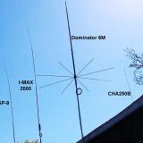
But a great antenna company called Solarcon has built a very unique antenna called the I-MAX 2000. This antenna is a nice 5/8 wave for CB at 27MHz the way it should be. But the special thing about this is, the I-MAX 2000 measures out to a sweet .64 wave on the 10 meter amateur band. It also uses a unique matching network unlike any other antenna uses. The network uses an inductance / capacitance connection to the main element. There is no direct connection to the main element. This makes the antenna very very broadbanded, and allows a good match for use on 17, 15, and 12 meters as well as 11 and 10 meters. It is actually a nice 1/2 wave on 15 meters.
For detailed information about the Solarcon I-MAX 2000, CLICK HERE
One other small note. You may have wondered that if you go above the frequency that the antenna is a perfect .64 wavelength at, doesn’t that go beyond the limit and the pattern would start to collapse? The answer is yes, but with an exception. Every 1/2 or a 5/8 wave becomes a .64 somewhere above it’s designed resonant frequency and may even go beyond the .64 limit. But the matching network in a 1/2 or 5/8 wave is also designed to be resonant at it’s 1/2 or 5/8 wave frequency. However, a .64 wave antenna’s matching network is designed specifically to be resonant as a .64 coil. So as you go above the resonant frequency, the matching network maintains the impedance match better allowing the maximum power efficiency. And most true .64 wave antennas are a .64 wave at slightly higher frequencies than the antenna was designed for. So as you go higher in frequency, you are still within the tolerance of the .64 limit.
No one is really sure about why more manufacturers have not developed and sold more of these fantastic .64 wave antennas. My only guess is that they were worried that the length was so borderline to being too long, that they decided to play it safe and stick with 5/8 wave antennas. But the .64 wavelength is so great, they blow away 5/8 and 1/2 wave antennas. I guess the only way to get their attention to make more .64 wave antennas is to call or email them and make a big stink about it.
By David – K3DAV (3/29/2012)





Last Comments