Calculations and Simulations with Pads and Feedback Amplifiers
The input match exactly at 10 MHz is changed little from before, a result we would expect. Even the angle is the same. However, it is much different at other frequencies.
Adding an Output Filter
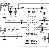
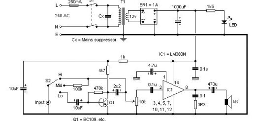
Wanting to show the behavior with termination in a narrow filter, we designed a simple double tuned circuit. We picked unusual inductors with an unloaded Q of 2000. While not off the shelf components, the software defined filter is one with low loss, which means that it should present a good load to the amplifier within the passband. (We could have just as well used a crystal filter, but did not want to get into those additional issues.) The 100 kHz bandwidth filter circuit is:

The 0.063 Ohm resistors in series with the 2 uH inductors simulate the unloaded inductor Q. R2 is another no-impact at RF component that keeps SPICE happy. (Don’t try to build this filter, for it would be very difficult to find or build inductors with such a high Qu.) The passband response and input match for the filter along are shown below :

The filter insertion loss is only 0.6 dB. While there is a good input match in the center of the filter, it quickly degrades as you depart from 10 MHz. S11 approaches 1 in the stopband, indicating total reflection. This behavior is typical of virtually all simple LC filters, as well as those with crystals or other similar resonators.
We now add the filter to the output of our amplifier with the total circuit shown below:

The input match looking into the amplifier at C1 is shown here:

The match is still good at 10 MHz with a return loss of 18.5 dB with an angle of -140 degrees. However, the match degrades to a return loss of only 3 dB in the upper stopband region. This could be a major problem if we tried to use this amplifier to terminate a switching mode mixer, especially one with a diode ring.
Continue to next page =>


Last Comments