Multimeters for Beginners. Meaning. Using. Short Theory.
Multimeters measure electrical quantities, and will at the very least measure Voltage, Resistance and Current. Usually they will have an AC and DC range. A multimeter is an essential item in any hobby electronics or repair workshop.
If you are interested in hobby electronics it is the number one item of test equipment. If you are interested in old radios it is the second most important item – the first being a Variac and isolation trannsformer (after all, you can’t repair anything if you’re dead.)
Normally, inexpensive instruments will have several ranges of DC measurements, but only 2 ranges for AC. As you pay more and more, they will have additional features and may measure “true RMS” AC volts (which we will talk about later), capacitance, frequency, temperature(!) and so on. They may be auto-ranging, which means that within reason they will not need to be switched from range to range when measuring a given physical quantity.
Multimeters may be “Analog” or “Digital”, and you may want one of each. Let’s begin by looking at how to apply a multimeter to a simple circuit. The pictures show an inexpensive digital meter.
Current measurement.

Voltage measurement.

Analog Meters
The basic analog meter uses a “Moving Coil” movement. Typically, this will be a 50 uA movement, meaning a current of 50uA will drive the meter needle to full-scale. The quality of an analog meter is expressed in Ohms/Volt – the higher the value, the better the meter, all other things being equal. Suppose the meter is rated at 20 000 Ohms/Volt (Typical of a reasonable meter) and has a 100mV range, then we might be led to assume the meter movement alone is used, which would give a resistance of 2000 Ohms for the meter windings. (In fact, it seems that even on the lowest range, the manufacturer uses a series resistor). Similar calculations will tell us that the meter has a 200 000 Ohm resistance on the 10 Volt range, and 2M on the 200 volt range. The reason the meter resistance varies on each range is that in a moving coil voltmeter circuit, the meter movement is placed in series with a resistor of the correct value for each measuring range. This resistor is called a multiplier.
The heart of an analog meter is the moving coil movement (Weston). The moving coil consists of many turns of hair-fine wire wrapped round an aluminium former. A small current through the coil generates a magnetic field and makes it attempt to move to the right or left. The hair spring resists the movement. The more the current, the greater the force against the hair spring and the greater the deflection of the armature, to which the pointer is attached. The pointer is counterbalanced by a counterweight so the movement can be used in any position.
In most valve radio circuits, a 20 000 Ohm/Volt meter is fine for estimating anode voltages etc. However, things go badly wrong when we attempt to measure things like grid bias and AVC voltages, since they all involve very high resistances and low voltages.
Here’s an example of what I mean. The circuit consist of a resistive voltage divider using two 3-Meg resistors. The AVC voltage is taken from the centre of the divider, and -21 volts is applied to the top of the divider. The capacitor is there to smooth out the fluctuations in audio, so we get essentially a DC value. Naturally we expect that at the centre of the divider we will measure -10.5 volts. We get out our trusty 20 000 Ohm/Volt meter and measure … ? Guess what – only -6 Volts (on the 100 Volt range or worse on the 10 Volt range. The problem is that the resistance of the multimeter is in parallel with the lower resistance of the potential divider. The meter resistance is 20 000*100 = 2 Meg on the 100 volt range. This means the lower resistor is now (2*3)/(2+3) = 1.2 Meg. The voltage across the lower resistor now becomes -21 * 1.2 /(1.2 + 3) = -6 Volts.
When you measure current, the meter must in series with the electrical circuit. Inside the multimeter itself, a shunt resistor is placed across the meter movement. Suppose we want to measure 1 Amp on our 50uA meter with 2000 Ohm movement, then from Ohm’s law, we need a voltage of 50 x 2000 / 1 000 000 = 0.1 volts. Neglecting the little bit of current flowing through the meter, this means we need a meter shunt of R = 0.1/1 = 0.1 Ohms . Again, be careful when measuring small currents produced by low voltages across low resistances. For example, in a simple circuit where a .01 volt supply has a load of 1000 Ohms – the current will be 10uA (right?). NOW – put your multimeter in series and the load resistance will increase by a considerable amount giving you a rubbish result. In practice you will seldom measure current directly like this, because it requires that you break the circuit. Normally, you will be measuring voltage across a resistor and calculating the current drawn from Ohms’s law.
As far as resistance measurements are concerned, you have to be careful to take into account the resistance of the meter leads when measuring low resistance values. Short the leads, note the resistance value and subtract that from the measured value.
Valve (and FET) Voltmeters – VTVMs
In order to overcome the problem of meter resistance when measuring voltage, valve voltmeters were devised. These have a constant input resistance, no matter what range you are on.

This feature is shared with digital multimeters, as we shall see. For some reason, many VTVMs (Vacuum Tube Volt Meters) have an input resistance of 11 Meg. If you go through our AVC example, I am sure you will agree that 11 Meg isn’t really high enough. That being the case, you will have to do the math every time you take a measurement. Unfortunately, it still means that the radio under test won’t work correctly while you are doing the measurement.
A very useful feature of VTVMs, is the ability to set them up as “centre zero” meters. This makes them ideal for aligning FM discriminators. Note that a VTVM does not need as delicate a meter movement as that required for conventional analog meter.
The downside of a VTVM is that you will only be able to buy one second-hand, and it will require repair/recalibration before you can use it. Generally, you can’t use a VTVM directly for current measurements.
Digital Multimeters
In common with valve voltmeters, digital multimeters have a constant input resistance. This should not be a surprise, since they share the same input circuitry. The inexpensive meters costing less tha R50-00 generally have a 1M input resistance, whilst their more expensive brethren have an input resistance of 10M Ohms.
If you are principally interested in transistor circuits and other low-voltage gadgetry, the least expensive meter will get you a long way. If, however, you are working with valve circuits, you might be measuring the screen grid voltage – around 200 Volts. On the analog meter 20 000 Ohms per volt, 500 volt range – you would be putting a 10 Meg load across the circuit. With the cheap digital meter you would be putting 1Meg across the circuit and would have to do the sums. For this reason, I would suggest going for a quality high input resistance instrument. (It doesn’t have to be a R3 500-00 rand investment.) if you are interested in valve circuitry.
By the way, the cheap instruments often have a “transistor tester” built-in. This is almost useless because any transistors you remove from a faulty circuit have leads way way too short to fit the tester. On the other hand, the “diode tester” is really useful.
Although digital meters have huge resolution (1 part in 2000 or 1 part in 20 000 ) that does not mean their accuracy is neccesarily all that great. In any case, do you really care if you have 185 volts on the screen grid or 190 volts ? – If you do, then it may reflect more about you than about the operation of the circuit.
AC Measurements
Picture yourself in the early part of the 20th century in Britain. Telephones were rare, radios were for the wealthy and – the power supply was often DC. A 230 Volt DC supply is easy to visualise – its simply what you would get from a large battery. Now imagine you have an electric kettle that takes about 10minutes to heat 2 pints of water (I haven’t done the math -so I don’t know if this is realistic) Assume the label on the kettle says it draws 1 kiloWatt. Now we know we have used 1 kW * 10 / 60 kWh or “units” to boil the water.
Now imagine that we get a letter through the post (There was no email in 1930) to say that our DC supply will be changed to AC. The supply utility doesn’t want us to throw away all our expensive “Swan Brand” kettles, so it has to supply a voltage that will do the same job. Now because AC varies from zero to a peak voltage, and then back down again to zero then to a negative peak – we need some sort of average to be 230 Volts, and the peak to be adjusted to give the same heating effect – namely 10 minutes to boil the water.
It turns out that to do this, the peak of the AC waveform has to equal 1.414 * 230 volts. Because 1.414 = 1 / (square root of 2), in AC parlance, 230 Volts is called the root mean square value. The problem is that whilst the foregoing is true for a sine wave AC voltage, it ain’t neccessarily so for other waveforms, such as sawtooth or modified sine wave, as provided by many inverters.
Analog multimeters simply use a rectifier to convert the AC voltage to DC. The manufacturers then often use a resistor network to fudge the instrument to give something approaching the correct reading. This is also the approach taken by the makers of inexpensive digital multimeters. (Confession: It is also the method I used to indicate gm in my valve tester…)
The problem is, that when you measure the output from a modified sine wave inverter with most simple multimeters, you get a wildly inaccurate result that is pretty meaningless.
To get reasonable results from your AC measurements, you need a circuit that converts AC to “true RMS” DC, such as the “Analog Devices” AD 736, but since I don’t recommend your making your own multimeter – be sure to be aware that the little extra you pay for a true RMS reading meter is worth it. Also be sure to read the instructions – its no good trying to measure the RMS value of an AC signal having a frequency much above a few kHz.. We’ll take a closer look at RMS and the AD 736 in experimenter’s corner.
What to buy?
It would be nice to recommend the best instrument on the market, but in all honesty, multimeters are subject to damage, either by dropping them from the workbench (how my Hioki has survived, I’ll never know) or by abuse of one sort or another. Yes – its careless to have the meter on the 10 Amp current range and then sticking the leads across a lead-acid battery. Its careless to have the meter on the 2 Volt range, and then stick 230 Volts across it. Again – the poor old Hioki has had a few resistors replaced, but somehow it soldiers on. There simply isn’t a multimeter in the world that isn’t going to be subject to abuse -and possibly have to be thrown away frown. (Tip: Always leave your meter on the highest range AC when you have finished with it.)
That being the case – perhaps its best to begin with a cheapy until careful habits are developed. I would begin with a 20 000 Ohm per volt analog meter if you’re doing valve circuits (Cost about +- R250-00). That leaves enough pocket money for an inexpensive (+- R50-00) 3 1/2 digit digital multimeter. Of course, if you are a very careful person like me, you can lash out on a “Fluke” or something that will provide you with measurements you can really trust. These days, you can purchase really fancy multimeters for around R1200-0 that automatically set the voltage range (making it hard to blow them) and that interface to a PC so you can log changes of voltage over a period of time.
For those who like “oldinstruments” – you may be able to get an AVO meter from somewhere. In my case, I bought new instruments, but they have lasted well and have gotten old like me.
A Note on Safety
Do read the manual that comes with your chosen testmeter. If it says it can only measure to 600 volts – believe it. It is not a great idea to be working on a valve transmitter or high power audio power supply (1200 volts at 500mA typically) and then take measurements with an ordinary meter. Believe me when I say its very painful to get a shock from a thing like that – assuming you live, that is.
Making your own multimeter
The only possible justification for doing this is that it is educational – plus, of course you have the satisfaction of using something you made yourself.

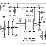
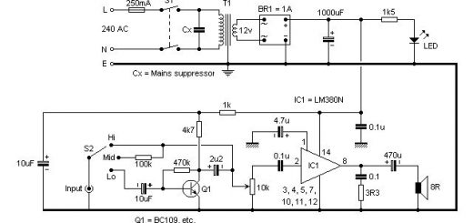
Here are some ideas, but you will end up spending more money than just going out and purchasing a meter. The circuit alongside is fairly straightforward, but very expensive.
To begin with, you’ll need a box to put it in. You could use a Ferrero Rocher sweet box. Complete with sweets, this will already cost MORE than an inexpensive digital multimeter.
Then there’s the meter itself – probably R60-00 or so? and finally there’s the battery and switches. DON’T get me started on the cost of dry batteries because I’ll start to rant.
I don’t really understand how a complete digital multimeter can cost almost the same as the 9 Volt battery you buy in the local hardware store.
Buying Second-Hand
When buying a second-hand meter(or any test equipment), always assume that its broken and needs fixing. Fixing, in this context includes calibration. That means – you’ll need a testmeter to fix your testmeter. Just bite the bullet and buy your first instrument(s). Thereafter, you can get your “pre-owned” instruments back into working condition.


Last Comments